Sonar Sensor/Arduino uno

using the Arduino Uno to create a Sonar Sensor.

using the Arduino Uno to create a circuit system that detects sonar waves/scape’s.

the wiring for this wasn’t that hard at all if anything it was very simple, however the coding was a little more confusing but i managed to get the hang of it, it was really cleaver how the Arduino translated the sonar into a visual aspect.

so the higher the voice or sound that was transmitted to the sonar sensor the higher the numbers climbed to on the computer screen and so on.

sonar sensor

Light Depending Resistor/ Arduino.

Light Depending Resistor (LDR).

a LDR does exactly what it says on the tin, it measure the amount of light around it and using the recordings it takes in, it alters the way the LED on the circuit behaves.

so the more light the LDR is sensing the more light the LED emits, the less light that is sensed the lest amount of light it emits and everything in between this allows you to make the LED fade in and out if you slowly cover and uncover the LDR.

light depending resistor

learning circuitry using the Arduino Uno.

we started to learn very basic circuitry using the Arduino Uno and bread board (the white circuit grid), these workshops were very simple and easy to learn from, I’ve never done circuitry with the Arduino before but it does make everything a whole lot easier and simplier to learn, from these workshops i learnt how to wire up circuits and write the codes which command what the Arduino  does.

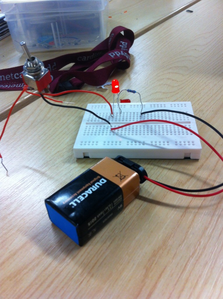
the coding is easy to get the hang of and make sense of all the terminology that i have to learn. to start with we got taught how to make a circuit board for just one LED light (image below).

circuit board one

once we got the circuit working we could mess around with how the LED behaves to do this we had to learn some coding for it, by the end of the lecture i had learnt how to put time delays in the coding so the LED would blink e.g. on for 1000 milliseconds and off for 300 milliseconds this make the LED blink very slow but if you just change the amount of seconds or milliseconds you can speed the blinking up or even slow it down.

Kinetic environments

this week we started our new Field lectures and workshops.

we started by having tutorials and little workshops on how to use the Arduino Uno circuit board (image below).

ArduinoUno_R3_Front

what is the Arduino uno?

The Arduino Uno is a microcontroller board based on the ATmega328 (datasheet). It has 14 digital input/output pins (of which 6 can be used as PWM outputs), 6 analog inputs, a 16 MHz ceramic resonator, a USB connection, a power jack, an ICSP header, and a reset button. It contains everything needed to support the microcontroller; simply connect it to a computer with a USB cable or power it with a AC-to-DC adapter or battery to get started.
The Uno differs from all preceding boards in that it does not use the FTDI USB-to-serial driver chip. Instead, it features the Atmega16U2 (Atmega8U2 up to version R2) programmed as a USB-to-serial converter.

“Uno” means one in Italian and is named to mark the upcoming release of Arduino 1.0. The Uno and version 1.0 will be the reference versions of Arduino, moving forward. The Uno is the latest in a series of USB Arduino boards, and the reference model for the Arduino platform; for a comparison with previous versions.